
The Overview of OSI Model
In the late 1970s, one project was administered by the International Organization for Standardization (ISO), while another was undertaken by the International Telegraph and Telephone Consultative Committee. These two international standards bodies each developed a document that defined similar networking models. In 1983, these two documents were merged to form a standard called The Basic Reference Model for Open Systems Interconnection. The standard is usually referred to as the Open Systems Interconnection Reference Model, the OSI Reference Model, or simply the OSI model.
The Open Systems Interconnection model (OSI model) is a theoretical model that characterizes and standardizes the communication functions of computer networks. So, the basic goal is to follow one standard while making the device communicating with each other even using different applications. To achieve and to work efficiently ISO created layer approached OSI model, which also helps in problem solving by understanding the error in communication path. (for example: everything is working as expected at Layer 3, then we know the problem is not at Layer 2 or Layer 1 and therefore the issue is above Layer 3 and not below Layer 3, so we need to find solution in upper layers .) Various aspects of OSI design evolved from experiences with the ARPANET, NPLNET, EIN, CYCLADES network and the work in IFIP WG6.1. The new design was documented in ISO 7498 and its various appendixes and white papers. The original version of the model defined seven layers.
Before going deep into the OSI model we need to understand why we need it? The basic need arrived when computer manufacturing business started booming and soon consumer and manufacturer realised that the inter device communication i.e., connection between two different vendors did not work based on the concepts portrayed in the TCP/IP. So, to solve this issue, ISO came with OSI model which has a set of standards and protocols that governs the communication function irrespective of the vendors/structure/technology.
OSI Model
The Open Systems Interconnection model (OSI model) is a theoretical model that characterizes and standardizes the communication functions of computer networks. So, the basic goal is to follow one standard while making the device communicating with each other even using different applications. To achieve and to work efficiently ISO created layer approached OSI model, which also helps in problem solving by understanding the error in communication path. (for example: everything is working as expected at Layer 3, then we know the problem is not at Layer 2 or Layer 1 and therefore the issue is above Layer 3 and not below Layer 3, so we need to find solution in upper layers .) Various aspects of OSI design evolved from experiences with the ARPANET, NPLNET, EIN, CYCLADES network and the work in IFIP WG6.1. The new design was documented in ISO 7498 and its various appendixes and white papers. The original version of the model defined seven layers.
In this model, a networking system was divided into layers. Within each layer, one or more entities implement its functionality. Each entity interacted directly only with the layer immediately beneath it, and provided facilities for use by the layer above it.
Below are the table of seven layers and the basic description of each.
Layer No. | Layer Name | Layer Description |
| 7 | Application | End user interface: here user or human can work, whatever user sees on device screen |
| 6 | Presentation | Syntax layer: here data encryption/decryption, code translation, data conversion, data compression etc. occurs |
| 5 | Session | Synchronisation: session establishment /termination/separation, session related supports been provided here |
| 4 | Transport | TCP/UDP selection: this layer provides reliable or unreliable connections for communication |
| 3 | Network | Path Selection: taking multiple parameters in consideration this layers provides best path to destination network |
| 2 | Datalink | Framing: this layer contains local area network (LAN) and media access control (MAC) features |
| 1 | Physical | Physical arrangement: cable, hubs, electrical signals, bits and bytes |
 The Application Layer
The 7th layer or we can say the starting phase of sender and the ending phase receiver in communication process, here whatever user see on his/her device screen which he/she intent to use for communication is known as application layer in OSI model for example internet explorer, email, file transfer application remote access, network management activities, client/server processes and most important application people are busy with today is chat messengers.
The Presentation Layer
This layer presents user the actual information from devices in user readable format. The colour you see on your screen or if you are reading this book on you device or the application icons you see on your device screen or watching videos and many more were all converted from the machine language to a human readable language (for example, EBCDIC to ASCII). By providing translation services, the Presentation layer ensures that data transferred from the Application layer of one system can be read by the Application layer of another system.
The Session Layer
The job of session layer is as simple as it sounds “session”, in session layer session between devices are created, terminated, separated and most importantly maintained till session is not terminated. For example if you are using your web browser to access information from www.yit.co.in your web browser which is nothing but and application goes on YIT web server to access information, here session layers creates session and maintains that session till it is not terminated. Here the devices each side of network generates session’s id so that web browser can facilitates to same app creating multiple session with same destination application, like you have tabs option on your web browser where you can create as many as session with www.yit.co.in.
The Transport Layer
Transport layer decides what type of connection to be used for particular sending application to do communication with end device application, TCP or UDP nothing but reliable (guaranteed delivery of data with acknowledgments) or unreliable (best effort delivery without acknowledgments). It’s like you need to decide while sending money to your friend or family from your location X to their location Y. Now you have plenty of option to do so, i.e. send money via bank to bank, money order, wire transfer, these all are reliable way of sending money where you get receipt (acknowledgment or TCP) for your transaction. Now, you cannot use options like every day people are traveling from location X to Y, you cannot just ask one of those to take your money for you and deliver it. It would be unsafe way of transactions. Now suppose you are at location X where only this book is available, some of your friends who are at location Y need this book. Here also you have plenty of option to courier them, if volume is high it may cost you more to deliver them, second option could be visiting transport like bus service which are going from location X to Y and asking favour from bus driver or conductor to just drop your parcel at your Y location stop, where your friend will go and collect it. Now this type of transaction will not get any receipt (no acknowledgment or UDP) also, not sure what time bus will reach or your friend will go to bus station to collect the parcel, that’s the reason UDP is called best effort delivery, another example like watching videos on youtube.com. If you are watching videos on slow link, you may miss some of the frames or you may get glitch, now here Youtube server is not bother to send those frames back which you missed it will be keep playing the video, if you want watch the missed part you need to play again, because video streaming is UDP connection, it does not have sequencing option like TCP where each packet is sequenced, so that receiver to know what is missed and regenerating that missed packet again by sending request to sender.
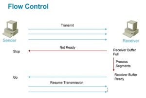
Flow Control
To allowing user to provide reliable transportation between devices TCP make sure that data is controlled while transferring, Flow Control is all about making sure that sender don’t send more packets when the receive buffer is already full, as the receiver wouldn’t be able to handle —an event that can result in lost data. To provide reliable data transport TCP creates connection-oriented communications session between devices, which make sure that the segment are acknowledged at the time of receiving, any segments not acknowledged are retransmitted. Segments are sequenced back into their correct order upon arrival at their destination.
Connection-Oriented Communication
In TCP, sender device first establishes a connection oriented session with receiver device. Below Figure shows the process of session. In it, both devices application programs begin by notifying their individual operating systems that a connection is about to be initiated. The two operating systems communicate by sending messages over the network confirming that the transfer is approved and that both sides are ready for it to take place. Once the required synchronization is complete, a connection is fully established and the data transfer begins. Cisco sometimes refers to this as a three-way handshake.

Once the connection established Fundamental, reliable, connection-oriented data transfer, datagrams are delivered to the receiving host in exactly the same sequence they’re transmitted; the transmission fails if this order is breached. If any data segments are lost, duplicated, or damaged along the way, a failure will transmit. The answer to the problem is to have the receiving host acknowledge receiving each and every data segment.
Windowing
Data throughput would be low if the sending device had to wait for an acknowledgment after sending each segment. In some cases most of the time senders and receivers hardware and software configuration can be different and processing of segments time may vary. The number of segments that sending device is allowed to send without receiving an acknowledgment for them is called a window. In above Figure the window size is 1. When a window size of 1 is configured, the sending machine waits for an acknowledgment for each data segment it transmits before transmitting another. In below figure the window size is 3. When window size is configured to 3 receivers send one acknowledgement for three segments and so on.

Reliable data delivery ensures the integrity of a stream of data sent from one machine to the other through a fully functional data link. It guarantees the data won’t be duplicated or lost. The method that achieves this is known as positive acknowledgment with retransmission. In above figure the sending machine transmits segments 1, 2, and 3. The receiving node acknowledges it has received them by requesting segment 4. When it receives the acknowledgment, the sender then transmits segments 4, 5, and 6. If segment 5 doesn’t make it to the destination, the receiving node acknowledges that event with a request for the segment to be resent. The sending machine will then resend the lost segment and wait for an acknowledgment, which it must receive in order to move on to the transmission of segment 7.
TCP vs UDP
| Features | TCP | UPD |
| Stands for | Transmission Control Protocol | User Datagram Protocol |
| Type of Connection | It is a connection oriented protocol | It is a connection less protocol |
| Examples | HTTP, FTP, SMTP, Telnet | DNS, DHCP, TFTP, SNMP, RIP, VOIP |
| Ordering of data packets | It rearranges data packets in the order specified | No ordering, the data packets of same message may be ordered differently |
| Speed of transfer | Comparatively slow | Comparatively fast |
| Reliability | Reliable | Unreliable |
| Header Size | TCP header size is 20 bytes | UDP Header size is 8 bytes |
| Fields | 1. Sequence Number, 2. AcK number, 3. Data offset, 4. Reserved, 5. Control bit, 6. Window, 7. Urgent Pointer, 8. Options, 9. Padding, 10. Check Sum, 11. Source port, 12. Destination port. | 1. Length, 2. Source port, 3. Destination port, 4. Check Sum. |
| Weight | It is heavier as it requires three packets to set up a socket connection, before any user data can be sent. TCP handles reliability and congestion control. | UDP is lightweight due to no ordering of messages, no tracking connections, etc. |
| Data Flow Control | TCP controls the flow of data
| UDP does not have an option for flow control |
The Network Layer
The purpose of network layer is to find best route to destination with the help of network protocols addresses such as IP address. Find best route to destination is known as routing where routers works efficiently to do calculation using different routing protocols and other layer three networking devices characteristics’. When a packet is arrived on a router interface, the destination IP address is checked. If the packet is not destined for the router, then the router will look up the destination network address in the routing table. Once an exit interface is chosen, the packet will be sent to the interface to be framed and sent out on the local network. If the entry for the destination network is not found in the routing table, the router drops the packet.
There are two types of packets are used at the Network Layer Data and route update packets:
Data Packets
The data packet is small part of actual data which is fragmented into single package and travel from source to destination on selected routing path in the network. The Internet Protocol (IPv4 and IPv6) is the most widely-used Layer 3 data carrying protocol and will be the focus further in this book. The below is the list of Internet Protocols also known as routed protocols:
- Internet Protocol version 4 (IPv4)
- Internet Protocol version 6 (IPv6)
- Novell Internetwork Packet Exchange (IPX)
- AppleTalk
- Connectionless Network Service (CLNS/DECNet)
Route Update Packets
As we know router finds best route to destination network, this task is achieved by sharing network route update information with the neighbour router, this information is nothing but route update packets. Various type of protocol can be used to share such information in internetwork; each protocol creates its own routing table with route update packets in the router by calculating programmed parameters, these protocol known as routing protocol. There are mainly two types of routing protocol Static and Dynamic. In this book will cover static routing and some of the dynamic routing protocols like RIP, RIPv2, EIGRP and OSPF.
Below figures explains the routing tables.
| Routing Table R1 | Routing Table R2 | Routing Table R3 | ||||||||
| Destination | Interface | Metric | Destination | Interface | Metric | Destination | Interface | Metric | ||
| 10.10.1.0 | Fa 0/0 | 0 | 10.10.1.0 | S 0/0 | 1 | 10.10.1.0 | S 0/0 | 2 | ||
| 10.10.2.0 | S 0/0 | 0 | 10.10.2.0 | S 0/0 | 0 | 10.10.2.0 | S 0/0 | 1 | ||
| 10.10.3.0 | S 0/0 | 1 | 10.10.3.0 | S 0/0 | 0 | 10.10.3.0 | S 0/0 | 0 | ||
| 10.10.4.0 | S 0/0 | 2 | 10.10.4.0 | S 0/0 | 1 | 10.10.4.0 | Fa 0/0 | 0 | ||
A routing table consists of directly connected networks and routes learned statically or dynamically. It is very important to know the routing table in depth. Learning the construction and lookup process of the routing table will help you diagnose any routing table issue. In above table you can find some of the entries created by routing protocols, below are complete entries you will see in cisco routers.
- Route source: Identifies whether the learned routes are directly connected network or learned using routing protocols by showing its code. Below is the output from one of the cisco router, which shows codes related to routing source.
Codes: C – connected, S – static, I – IGRP, R – RIP, M – mobile, B – BGP
D – EIGRP, EX – EIGRP external, O – OSPF, IA – OSPF inter area
N1 – OSPF NSSA external type 1, N2 – OSPF NSSA external type 2
E1 – OSPF external type 1, E2 – OSPF external type 2, E – EGP
i – IS-IS, L1 – IS-IS level-1, L2 – IS-IS level-2, ia – IS-IS inter area
* – candidate default, U – per-user static route, o – ODR
P – Periodic downloaded static route
- Destination network: Next thing it shows is destination network entry consists of directly connected networks and routes learned statically or dynamically. It is shown in above diagrams routing table.
- Administrative distance: Administrative distance value or AD value, which is pre-assigned to all learned networks, which helps router to decide which routing protocol, should be used while creating routing table, Identifies the trustworthiness of the route source. Below are some well-known AD values of routing protocols.
| Routing protocol | Route source | Default Distance Values |
| Directly Connected interface | C | 0 |
| Static route | 1 | |
| Internal EIGRP | D | 90 |
| IGRP | I | 100 |
| OSPF | O | 110 |
| Intermediate System-to-Intermediate System | IS-IS | 115 |
| Routing Information Protocol (RIP) | R | 120 |
| Exterior Gateway Protocol (EGP) | E | 140 |
| External EIGRP | EX | 170 |
| Internal BGP | B | 200 |
- Metric: As learned before that routing protocol perform calculation using pre-configured formulas to find best path to the destination, the result value of calculation is called as For example if you have configured EIGRP in your network and EIGRP finds multiple paths to reach to the destination, to know which path is the best path router will check the metric of all paths, which identifies the value assigned to reach the destination network. Lower values indicate preferred routes.
- Next hop: Identifies the IPv4 address of the next router to forward the packet via this address toward the destination.
- Route timestamp: It is a time since the route was last learned.
- Outgoing interface: Identifies the exit interface to use to forward a packet toward the destination.
Data-Link Layer
Data Link layer will ensure that the messages are delivered to the appropriate device in a LAN. The Data Link layer formats the message, called a frame, and adds a customized header containing the hardware destination and source address known as MAC address (Media Access Control Address) and will converts messages from the Network layer into bits for the next layer to transmit. It’s the Data Link layer that’s responsible for the actual unique identification of each device that resides on a local network.
The data link layer has two sub layers: logical link control (LLC) and media access control (MAC).
Logical Link Control (LLC)
The uppermost sub layer LLC, Responsible for identifying Network layer protocols and then encapsulating them. Also, optionally provides flow control, acknowledgment, and error notification. The LLC provides addressing and control of the data link. It specifies which mechanisms are to be used for addressing stations over the transmission medium and for controlling the data exchanged between the originator and recipient machines.
Media Access Control (MAC)
When devices attempt to use a medium simultaneously, frame collisions occur. Data-link protocols specify how devices detect and recover from such collisions, and may provide mechanisms to reduce or prevent them. Some of the well-known layer 2 protocols are Ethernet for local area networks (multi-node), the Point-to-Point Protocol (PPP), HDLC and ADCCP for point-to-point (dual-node) connections.
The IP address in network layer is logical address and can be change according to change in network configuration or user move with device from one location to another, now to tracking down the exact device in network we need unique identification addressing scheme, for that MAC address or hardware address comes handy. A MAC address is burned on hardware with the international standards by a manufacturing company.
Further in the book we will learn about switches and bridges and other layer 2 devices.
The Physical Layer
The last layer of OSI model performs the job of sending and receiving bits, yes the 0’s and 1’s. The physical layer consists of the electronic circuit transmission technologies of a network which specifies the electrical, mechanical, procedural, and functional requirements for activating, maintaining, and deactivating a physical link between end devices. This layer is also where we identify the interface between the data terminal equipment (DTE) and the data communication equipment (DCE). The DCE is usually located at the service provider, while the DTE is the attached device. The services available to the DTE are most often accessed via a modem or channel service unit/data service unit (CSU/DSU).
Above we have seen all 7 layers in details and their responsibilities in the network. Each layer performs codding and encoding of data by encapsulating and de-encapsulating required fields and creating new form of data unit for each lower and higher layer called Protocol Data Unit (PDU).
About me

Mr. Naresh Rathod
Sr. Corporate Trainer and IT Consultant
ACSA, ACMA, AMCP, CCNA, CCNA Wireless, CCNP R&S, CCNP Wireless, ITIL, CBNSFE, MCSA, CompTIA A+, CompTIA N+